Weights Stay Put, Topology Changes: Four-GPU Hybrid Parallelism for Hunyuan Image 3.0
Phase-Aware TP4-to-TP2+SP2 Inference Without Inter-Phase Weight Movement
TL;DR
A single T2I or TI2I inference run in Hunyuan Image 3.0 comprises two computational phases with distinctly different characteristics: autoregressive generation (AR) first, followed by diffusion denoising (denoise). Token-by-token AR generation benefits more from Tensor Parallelism (TP), which shards the model weights more finely; denoise operates on longer image-token sequences and is better suited to Sequence Parallelism (SP), which distributes sequence computation. Using a single parallel strategy throughout the inference pipeline forces one phase to compromise for the other.
LightX2V adopts phase-aware hybrid parallelism across four GPUs: AR prefill/decode runs with TP4, then switches to TP2+SP2 for diffusion denoising.
The proposed parallel-switching scheme avoids weight movement by relying on one key observation: SP does not shard weights. Each physical rank in denoise holds a local TP2 shard that is not further partitioned by SP, while the local weights required by that same physical rank under AR TP4 are exactly a micro subset of its denoise-resident TP2 shard. The AR phase therefore activates only that subset, while denoise activates its parent TP2 shard, with no need to reconstruct or exchange weights at the phase boundary.
This observation allows the model to initialize directly from the official checkpoint without offline weight conversion. Let M denote the complete set of model weights. Parameters that require TP are organized by storage TP2 into two rank-local shards, A and B, while parameters that do not participate in TP are replicated in both A and B. Because both SP ranks in denoise require the same TP2 weights, the resident layout across four GPUs becomes A, B, A, B. On the AR side, resident shards A and B each contain two complementary micro-shards, namely (A=[a1,a2]) and (B=[b1,b2]). Physical ranks 0, 1, 2, and 3 activate (a1, b1, a2, b2), respectively, and map to logical TP4 ranks 0, 2, 1, and 3. When an ordered output is required, the gathered physical outputs are read in rank order 0, 2, 1, and 3 to recover canonical TP4 shard order (a1, a2, b1, b2), while the resident weight tensors remain in place. On the denoise side, each rank uses its full A/B shard and enables SP2. Both phases share the same resident weights, so the phase boundary involves no model reload, weight repacking, or cross-GPU weight movement.
The MoE portion of denoise introduces an additional challenge: the micro-major layout of the resident TP2 weights cannot be represented by a single invocation of the standard FlashInfer fused-MoE operator. LightX2V therefore adds a multi-micro-shard MoE path. The two micros on each rank share one route permutation and one set of expert offsets, each performs the required grouped GEMMs, and the path executes routing-scale and top-k finalize only once at the end.
In the current four-GPU measurements, the hybrid scheme achieves both the lowest AR per-token latency and the lowest DiT per-step latency for the two tasks:
| Task | AR time/token | DiT one step |
|---|---|---|
| T2I hybrid | 46.333 ms | 285.096 ms |
| TI2I hybrid | 45.608 ms | 336.162 ms |
These results show that the hybrid scheme achieves strong inference performance on both tasks.
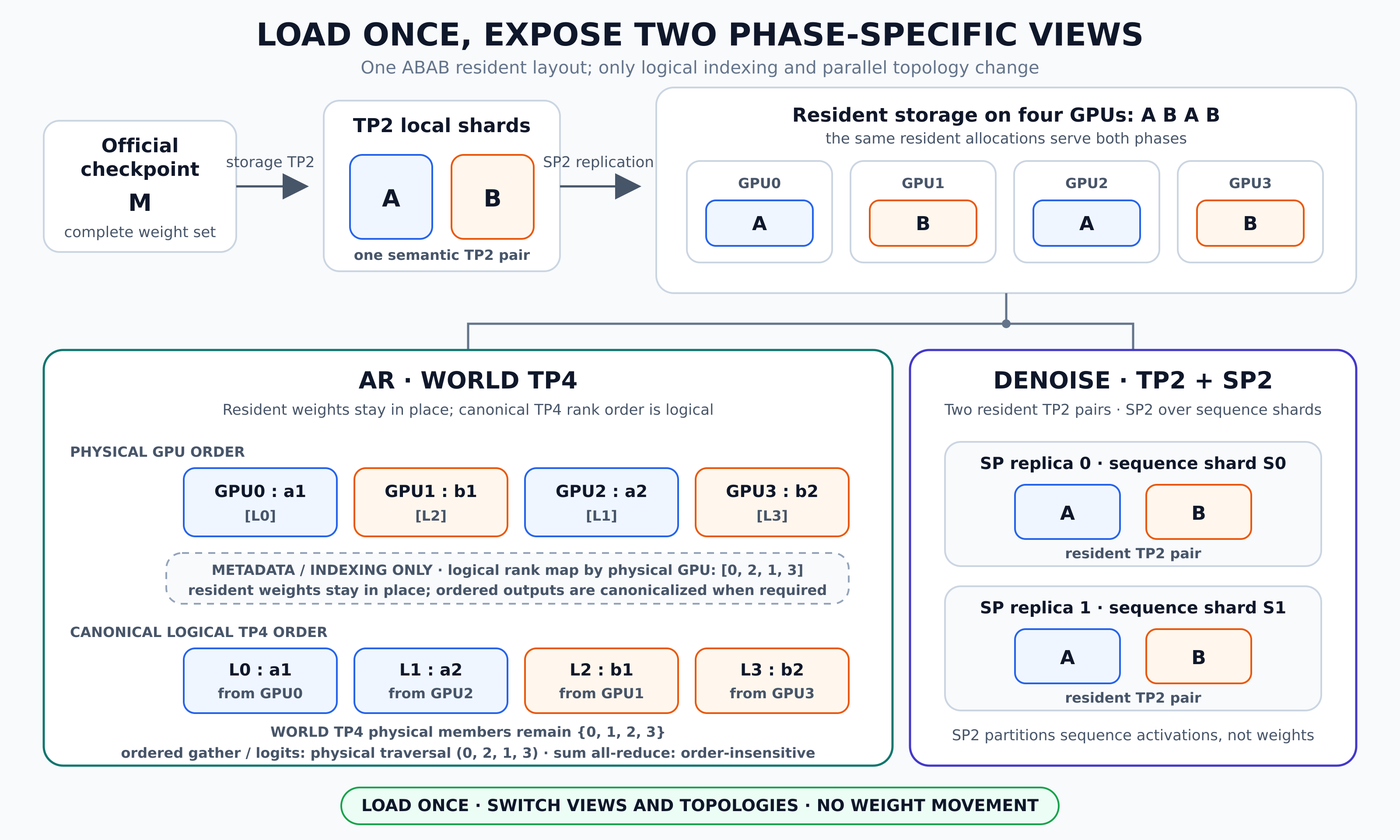
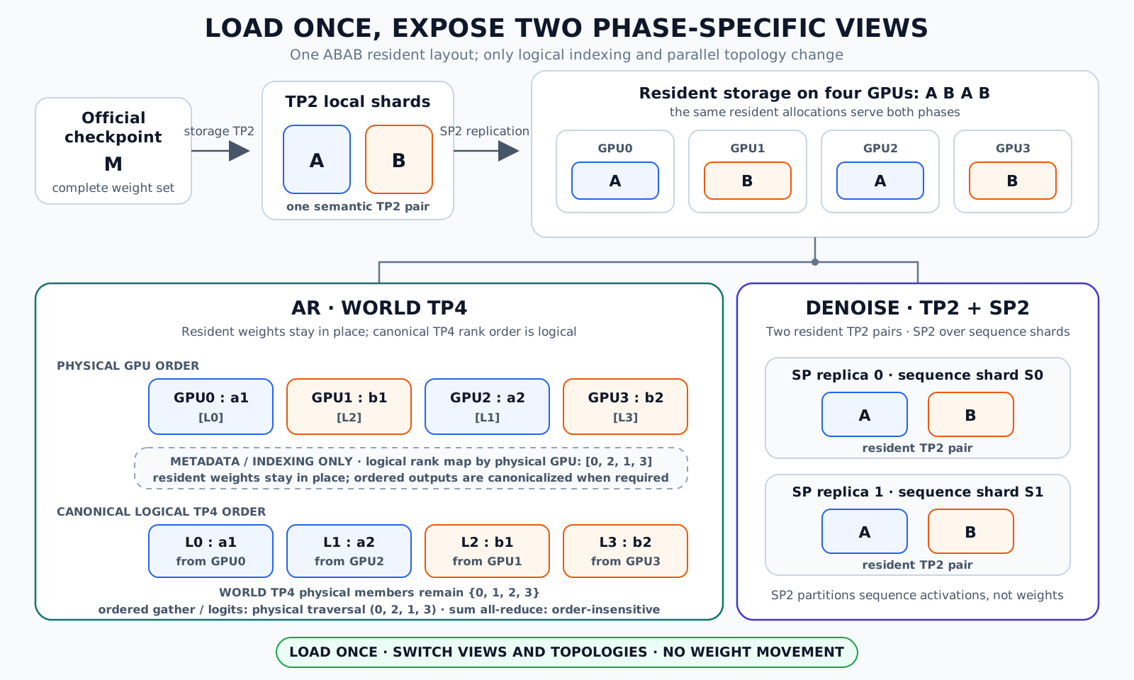
Figure 1: The official weights M form a storage-TP2 A/B pair and an ABAB resident layout. Under AR, physical order a1, b1, a2, b2 maps to canonical logical TP4 order a1, a2, b1, b2 through the physical-to-logical rank map [0, 2, 1, 3]; denoise reuses the same allocations as two TP2 pairs with SP2. SVG source
1. Why One Model Needs Two Parallel Topologies
Image generation in Hunyuan Image 3.0 is not a single-phase workflow. The model first performs AR prefill and then decodes token by token to generate the text or chain of thought used for subsequent image synthesis. The pipeline then constructs the diffusion input and repeatedly executes denoise steps over the image-token sequence. The two phases share model weights, but differ in sequence length, invocation granularity, and communication characteristics.
1.1 AR: The Token-by-Token Path Needs Finer Weight Sharding
AR prefill processes the entire context in one pass, whereas each decode step adds only a small number of tokens. For the four-GPU Hunyuan Image 3.0 workload measured in this article, further partitioning along the sequence dimension with SP does not provide enough local computation to amortize communication and scheduling overhead.
TP4 further partitions the linear layers, attention projections, and MoE weights across four ranks. Each GPU performs the local computation for its corresponding shard, and the results are then combined through collectives. On the repeatedly executed decode path, this approach reduces per-GPU computation while keeping the complete token sequence involved in every layer.
1.2 Denoise: Long Image Sequences Create Room for SP
The image-token sequence is longer during denoise, and the same Transformer blocks are executed repeatedly across multiple denoise steps. SP can distribute the computation and memory footprint of attention and activations along the sequence dimension, while retaining TP2 to accommodate the large model weights.
In the current four-GPU topology, TP2+SP2 allows two TP2 groups to process one sequence shard each. Within an SP group, Ulysses attention uses all-to-all communication to transform between sequence shards and head shards, then returns to sequence shards after attention completes. KV All-Gather SP is also supported: each rank retains its local Query sequence shard, gathers the complete K/V through All-Gather, performs Attention locally, and keeps the output in a sequence-sharded layout. After all Transformer blocks finish, the complete sequence is assembled along the SP group.
Fixed TP4 misses the opportunity to exploit long-sequence parallelism in denoise, while fixed TP2+SP2 cannot fully realize the token-by-token advantage of AR TP4. This leads to the fundamental conclusion behind the design: the most suitable parallel topology changes with the inference phase. The optimization target should therefore be a complete phase-adaptive parallel plan, rather than an isolated choice of TP or SP for the entire model.
2. Design Goals
The constraints are explicit:
-
The available resources are four H200 GPUs.
-
Load the official checkpoint directly, without an offline weight-conversion tool.
-
Initialize the weights into a single resident layout.
-
Use TP4 for AR and TP2+SP2 for denoise.
-
Do not reload, move across GPUs, or repack weights during a phase switch.
This is neither a general-purpose tensor-resharding framework for arbitrary TP/SP degrees nor a serving scheduler that selects parallel strategies dynamically according to online request load. The current implementation addresses a more specific problem: enabling the two execution phases of Hunyuan Image 3.0 to use their respective preferred topologies on a fixed four-GPU setup, while maintaining one stable set of resident weights.
3. Main Idea: Switching Between TP4 and TP2+SP2 Through the Weight-Subset Relation
The key question is: if the two topologies require different weights, how can the system switch between them without moving weights?
The answer lies in a containment relation discovered and exploited in the four-GPU layout: the local weights required by each GPU under AR TP4 are exactly a subset of the weights resident on that GPU under denoise TP2+SP2.
3.1 SP-Side Weights
SP partitions the input sequence and activations, while TP partitions weights along parameter dimensions. In this article, “SP-side weights” refers to the local resident TP2 weight shard held by each physical rank to execute its local sequence shard under the denoise TP2+SP2 topology; this weight shard is not further partitioned by SP.
Let the local TP2 shards for denoise be A and B (Section 4 explains how they are derived from the complete weights M), and decompose them further as follows:
A = [a1, a2]
B = [b1, b2]
The A/B pair is replicated across the two SP ranks, producing the following resident layout across four GPUs:
rank: 0 1 2 3
denoise resident: A B A B
[a1,a2] [b1,b2] [a1,a2] [b1,b2]
In physical-rank order, the four local shards activated by AR TP4 are a1, b1, a2, and b2. Placing each shard back into its resident tensor reveals the per-rank containment relation:
| Physical rank | Denoise/SP-side resident weight | AR TP4 active weight | Containment |
|---|---|---|---|
| 0 | A = [a1, a2] | a1 | a1 ⊂ A |
| 1 | B = [b1, b2] | b1 | b1 ⊂ B |
| 2 | A = [a1, a2] | a2 | a2 ⊂ A |
| 3 | B = [b1, b2] | b2 | b2 ⊂ B |
Let W_res(r) denote the weights resident on physical rank r during denoise, and let W_AR(r) denote the active AR weights. Then:
W_AR(r) = micro_view(W_res(r), local_micro_id(r))
W_AR(r) ⊆ W_res(r)
For projections that participate in TP, AR uses a strictly smaller micro subset. For replicated parameters such as norms and routers, both phases use the same parameters. It is therefore more accurate to express the relationship over the complete rank-local parameter set as W_AR(r) ⊆ W_res(r).
This relation is the foundation for switching the hybrid-parallel topology without weight migration. The AR phase exposes only one micro view of the parent tensor. Upon entering denoise, the system does not need to retrieve any missing portion from another rank; it simply switches the active view back to the full A or B tensor that is already resident on the local GPU.
3.2 Why This Subset Relation Covers Exactly Four AR Shards
The three current parallel degrees satisfy:
storage TP size = 2
AR TP size = 4
denoise SP size = 2

micro_shard_count
= AR TP size / storage TP size
= 4 / 2
= 2
= denoise SP size
A storage TP2 shard can be divided into exactly two TP4 micro-shards, and it also has exactly one replica on each of the two SP ranks. This makes it possible to assign:
SP rank 0 replica → select micro0
SP rank 1 replica → select micro1
Thus, the two replicas of the same storage shard contain identical data during denoise but activate different micros during AR. Together, they cover exactly all the shards required by TP4. The implementation validates this condition explicitly:
AR_TP / storage_TP == denoise_SP
This is not an incidental rank-numbering trick; it is a structural constraint required by this no-movement layout. Other parallel degrees can use the same approach only if they preserve the same one-to-one replica-to-micro mapping.
3.3 What a Phase Switch Actually Does
The complete execution sequence is shown below. The upper track represents the actual compute phases, while the green swimlane at the bottom indicates that the ABAB resident weights remain at their original addresses throughout the pipeline.
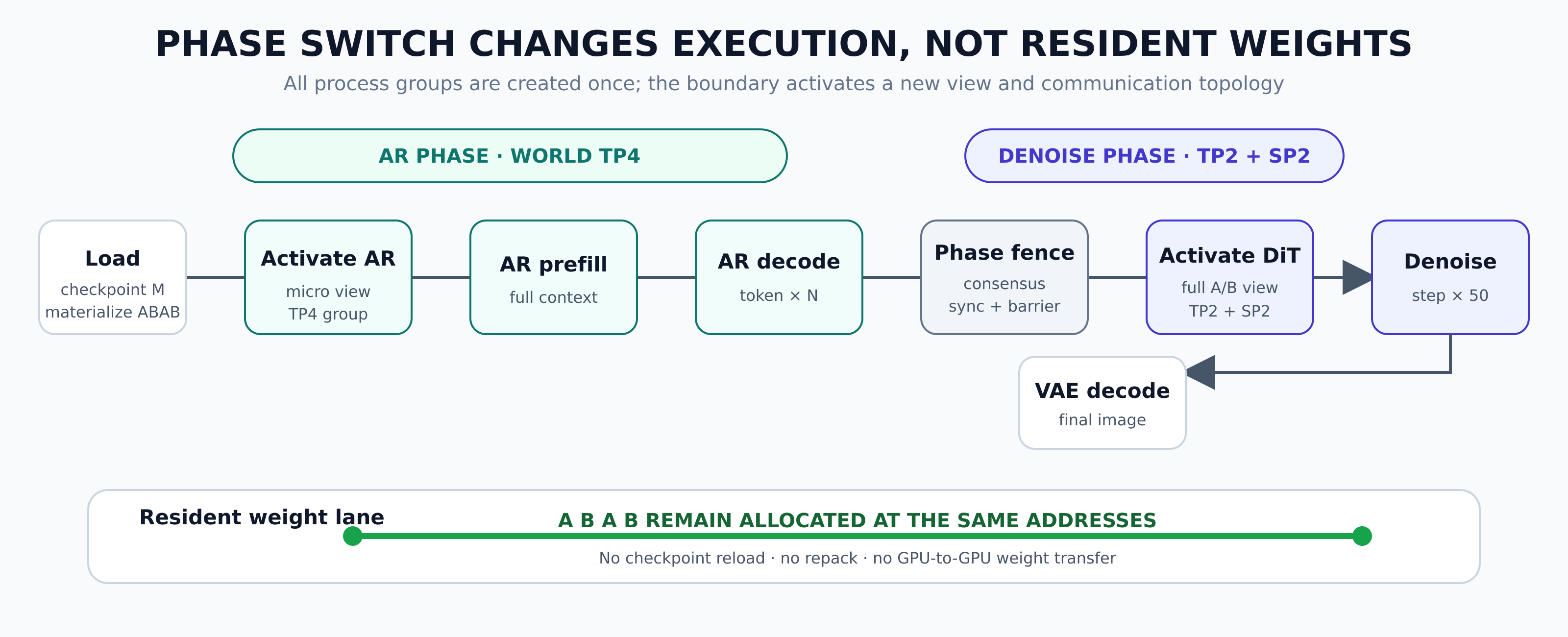
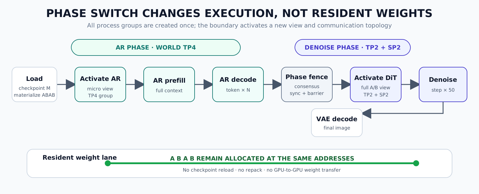
Figure 2: A phase switch activates a new local weight view and communication topology without changing the addresses of the resident weights. SVG source
This process does not create process groups at the phase boundary, nor does it create, copy, or reorder weight tensors. It activates the pre-created groups for the current phase, while the weight-side switch simply changes the active view from the micro subset W_AR(r) back to the already resident parent tensor W_res(r).
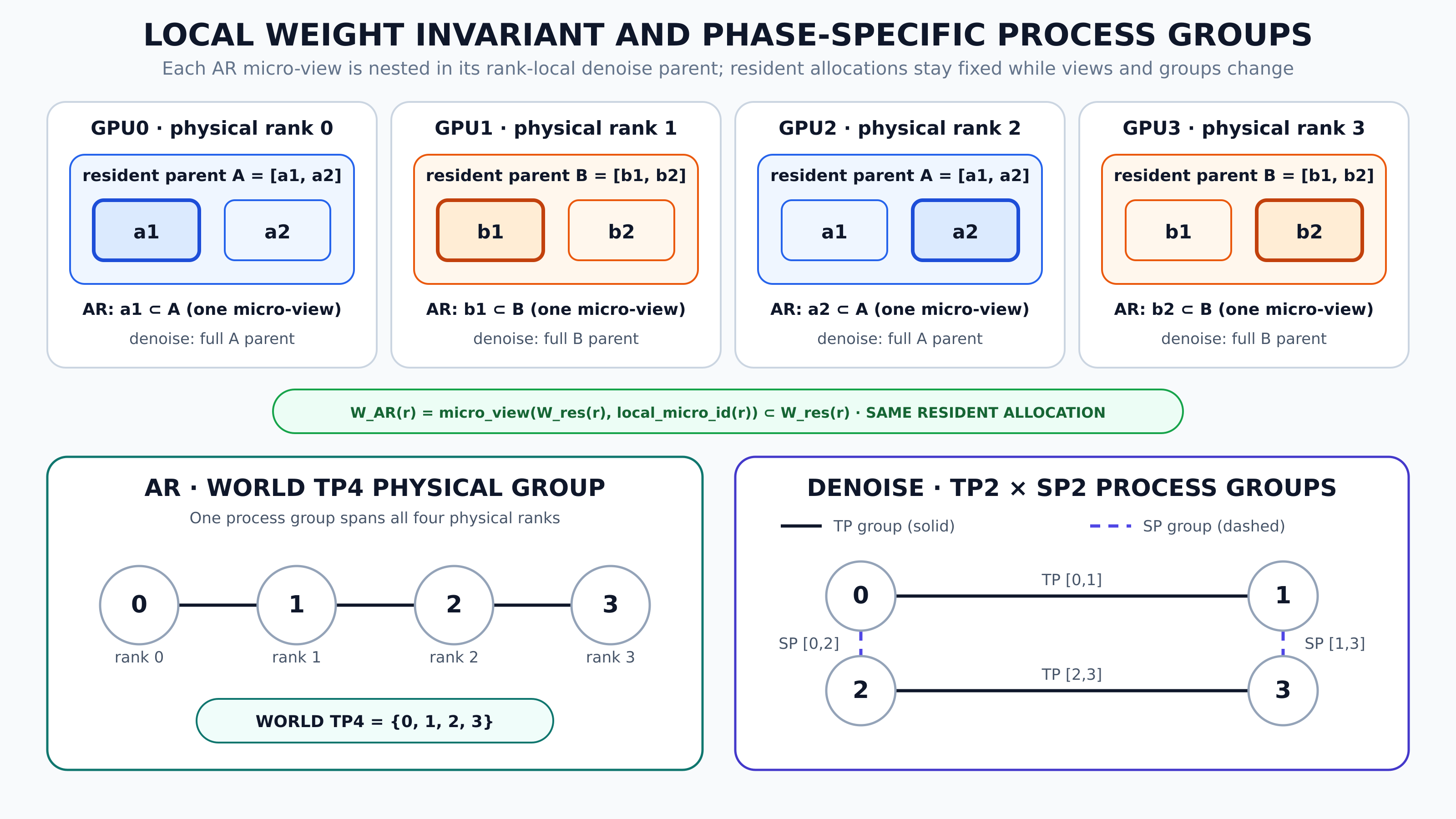
Figure 3: On each physical rank, the AR micro-view is already nested in its local denoise TP2 parent. Resident allocations stay fixed while execution switches from one WORLD TP4 physical group to denoise TP groups [0,1]/[2,3] and SP groups [0,2]/[1,3]. SVG source
4. From Complete Weights M to Resident TP2 Shards and TP4 Views
Switching communication groups alone is not enough. Hunyuan Image 3.0 is an 80B-class model, making it impossible to replicate the complete weights across all four GPUs. To understand where A, B, and ABAB come from, we begin with the complete model weights M in the official checkpoint.
4.1 How the Complete Weights M Are Split into A and B
Here, M denotes the complete set of model parameters rather than a single matrix. For clarity, the TP2 weights can be abstracted as:
complete model weights M
│
├── storage TP rank 0 → A
└── storage TP rank 1 → B
A and B are each a “local parameter set” that can participate in model execution on one GPU: they hold complementary shards for TP parameters and identical copies for replicated parameters. The computation represented by the complete weights M is recovered only when the TP shards in A and B are combined according to the semantics of each layer.
Different parameters cannot all be mechanically partitioned along the same dimension. Let W denote the weight of a linear layer in the official checkpoint:
-
A column-parallel projection is split along the output dimension. Conceptually, this can be written as
W_A = W[0:O/2, :]andW_B = W[O/2:O, :]. -
A row-parallel projection is split along the input dimension. Conceptually, this can be written as
W_A = W[:, 0:I/2]andW_B = W[:, I/2:I]. -
Fused QKV is assigned by complete KV-head groups and cannot be cut in the middle of a KV group.
-
Fused gate/up must be split along the output dimension while preserving the paired semantics of gate and up.
-
Norms, MoE routers, and other parameters without a declared TP split type remain replicated instead of being forcibly divided in half.
Therefore, “splitting the complete weights M into A/B” means organizing TP2 parameters according to operator semantics, rather than applying a single uniform physical partition.
4.2 Why A/B Becomes ABAB Across Four GPUs
Denoise uses TP2+SP2. SP partitions sequences and activations, not model weights, so every SP rank must own a complete TP2 rank pair. In the four-GPU mesh:
storage TP rank
0 1
SP rank 0 / mesh row 0 GPU0 A GPU1 B
SP rank 1 / mesh row 1 GPU2 A GPU3 B
The mapping from physical rank to storage TP rank is:
storage_tp_rank = physical_rank mod 2
Ranks 0 and 2 therefore receive local parameter set A from TP rank 0, while ranks 1 and 3 receive local parameter set B from TP rank 1. In physical-rank order, this becomes:
physical rank: GPU0 GPU1 GPU2 GPU3
resident shard: A B A B
ABAB is not an additional checkpoint format created by the design. It is the natural four-GPU resident layout produced by replicating storage TP2 across each SP replica. The model still reads from the same official checkpoint; each process selects A or B according to its storage TP rank.
Once denoise is active, TP group [0,1] uses the first A/B pair, TP group [2,3] uses the second A/B pair, SP group [0,2] connects the two A ranks, and SP group [1,3] connects the two B ranks. This preserves identical TP-shard semantics at both endpoints of SP communication.
4.3 Exposing TP4 Micro Views from A/B
To run AR with TP4, each TP2 shard is further divided logically into two micro-shards:
A = [a1, a2]
B = [b1, b2]
During AR, each physical rank selects one local micro view:
| Physical rank | Resident shard | Local micro | AR active view | Logical TP4 rank |
|---|---|---|---|---|
| 0 | A | 0 | a1 | 0 |
| 1 | B | 0 | b1 | 2 |
| 2 | A | 1 | a2 | 1 |
| 3 | B | 1 | b2 | 3 |
It is important to distinguish physical execution order from the canonical logical weight order:
physical rank order: a1, b1, a2, b2
Logical TP order: a1, a2, b1, b2
The logical TP rank is determined by:
logical_tp_rank
= storage_tp_rank × micro_shard_count
+ local_micro_shard_id
Both the storage TP size and the micro-shard count are 2, so physical ranks 0, 1, 2, and 3 map to logical TP ranks 0, 2, 1, and 3, respectively.
For the sum all-reduce of row-parallel outputs, participant ordering does not affect the result. Ordered all-gathers, such as those used for vocabulary logits, must reorder the physical outputs according to (0, 2, 1, 3) to recover the correct vocabulary-shard order.
4.4 How Standard Linear Layers Switch Views
QKV cannot be split arbitrarily along the raw fused dimension; the storage shard is selected by complete KV-head groups. The official fused gate/up layout is [gate_all, up_all], which is reorganized during initialization as:
[gate_micro0, up_micro0, gate_micro1, up_micro1]
This allows one AR micro projection to be obtained as a contiguous view, while denoise can use both micros from the same resident weights.
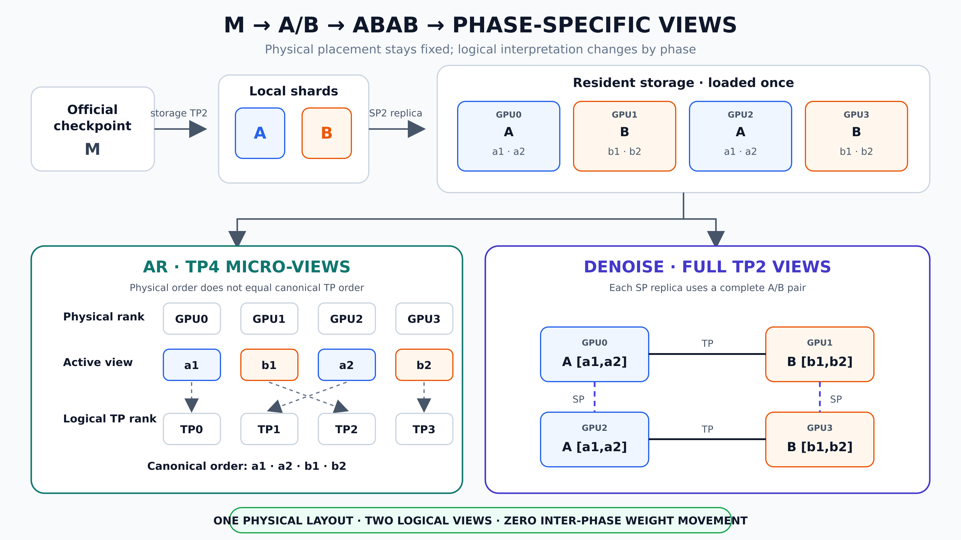
Figure 4: AR must map physical-rank order to canonical TP4 order, while denoise directly uses the complete A/B shards. SVG source
5. Why the MoE Layout Becomes the Critical Obstacle
In the engineering implementation, the most challenging part of hybrid parallelism is not switching communication groups, but enabling denoise to efficiently consume the micro-shard MoE weights prepared for AR TP4.
On each storage TP rank, the resident MoE pack is organized as follows:
W1: [micro=2, expert=64, 1536, 4096]
W2: [micro=2, expert=64, 4096, 768]
Their physical linear order is micro-major: all 64 experts of micro0 are stored first, followed by all 64 experts of micro1. A standard TP2 expert view, however, requires micro0 and micro1 to be grouped by expert.
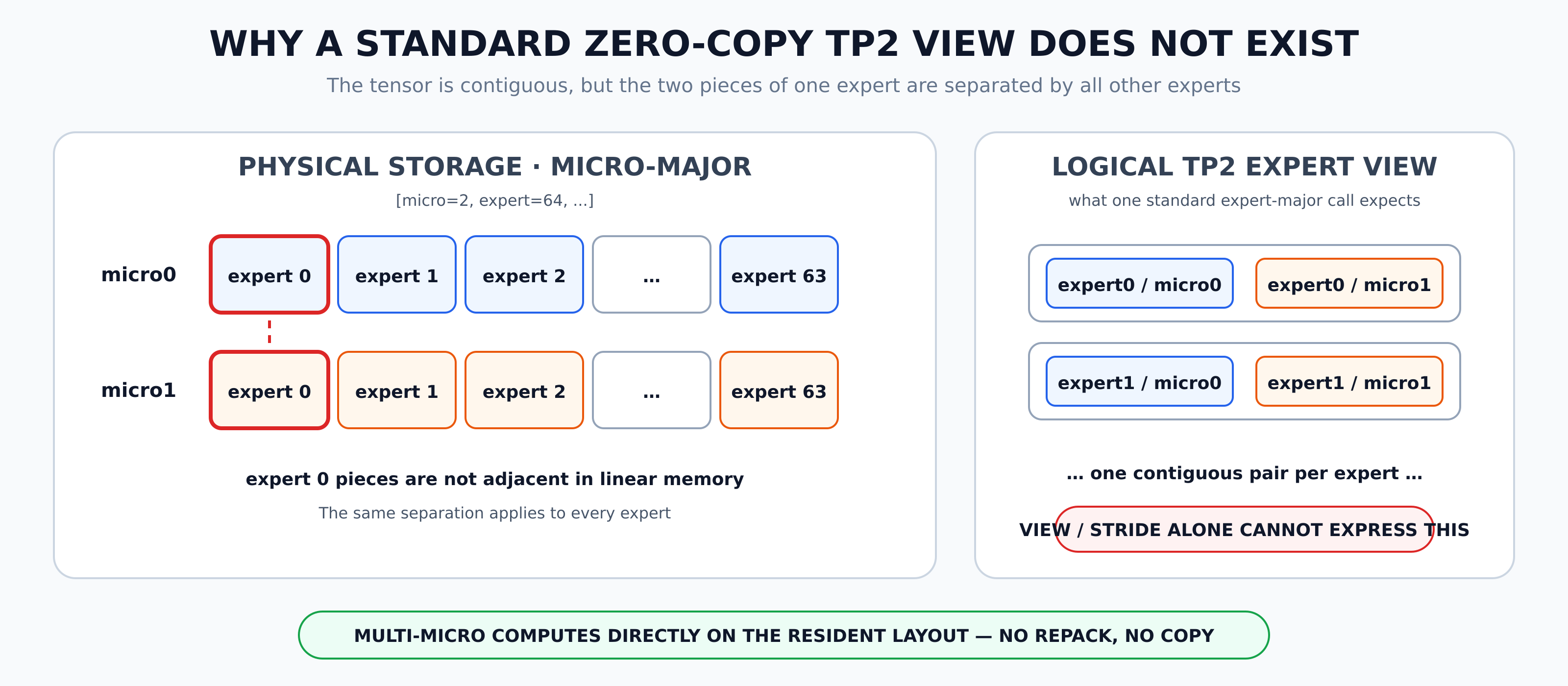
Figure 5: The two micro-shards of the same expert are not adjacent in physical memory, so a standard TP2 expert-major layout cannot be constructed using only an ordinary view or stride. SVG source
Although the entire pack is a contiguous tensor, the two micro-shards of a given expert do not form a standard contiguous expert-major weight. Without copying data, an ordinary view or stride transformation cannot make the micro-major layout appear as though each expert has the full intermediate dimension.
One option is to concatenate the weights again before denoise, but that requires additional GPU memory and a copy at the phase boundary. Another option is to pass micro0 and micro1 separately through FlashInfer fused-MoE and then add the two results. The two pairs of GEMM1/GEMM2 operations are mathematically necessary, but two complete fused-MoE invocations also duplicate:
-
route permutation;
-
expert offsets;
-
dispatch/finalize workspace;
-
route order restoration;
-
routing score;
-
top-k output reduction.
What should actually be eliminated is not the GEMM work for the two micro-shards, but the duplicated dispatch and finalize operations.
6. Multi-micro-shard Fused MoE
LightX2V adds a dedicated denoise interface, lightx2v_multi_micro_fused_moe. Instead of rearranging the resident weights, it allows the two micro-shards to share the same routing map.
6.1 One Routing Pass Shared by Two Micro-shards
The following figure compares two independent FlashInfer dispatches with the shared-routing multi-micro path. Both sides retain the four necessary GEMMs; the right-hand side eliminates only the duplicated route preparation and finalize operations.
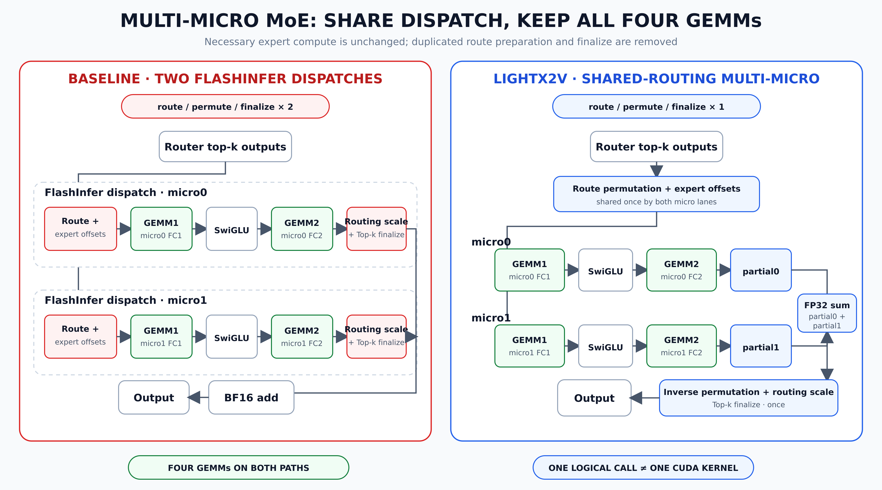
Figure 6: Multi-micro shares routing metadata and performs finalize only once; one logical interface invocation does not imply a single CUDA kernel. SVG source
The router produces expert IDs and routing scores with shape [num_tokens, top_k]. The operator flattens the expert IDs, sorts them by expert, and generates permuted_to_expanded. This permutation identifies the original token associated with each sorted route while placing inputs assigned to the same expert into contiguous ranges for the grouped GEMM.
Next, bincount(...).cumsum(...) generates offsets for the 64 experts. The input undergoes index_select only once according to this permutation; micro0 and micro1 share the same permuted input, route permutation, and offsets.
Each micro-shard executes grouped GEMM1 → split gate/up → SiLU(up) × gate → grouped GEMM2.
The two GEMM2 operations produce BF16 partial outputs of the same shape. The Triton path first builds the inverse permutation, then reads both partial outputs by original token and top-k slot in the finalize kernel:
output[token]
= Σroute routing_scale[token, route]
× (micro0_partial + micro1_partial)
The two partial outputs are first added in FP32, the routing score is applied only once, and the top-k reduction is likewise performed only once.
6.2 “One Invocation” Does Not Mean “One CUDA Kernel”
The denoise layer invokes the logical LightX2V MoE interface only once, but that interface still contains:
-
route sort, count, and input indexing kernels;
-
two grouped GEMM1 operations;
-
SwiGLU;
-
two grouped GEMM2 operations;
-
permutation inverse;
-
Triton finalize.
The multi-micro path shares one set of routing metadata and performs final reduction only once. It is neither a single CUDA kernel nor a reimplementation or wrapper of flashinfer_cutlass_fused_moe. The custom denoise path does not call the official FlashInfer fused-MoE; each AR rank uses only one micro-shard and therefore continues to call the official FlashInfer CUTLASS fused-MoE.
6.3 Engineering Implementation
The entry points are located in:
-
lightx2v/common/ops/moe/multi_micro_fused_moe.py -
lightx2v/models/networks/hunyuan_image3/weights/common.py -
lightx2v/models/networks/hunyuan_image3/infer/transformer_infer.py
7. End-to-End Data Flow for AR and Denoise
7.1 AR TP4
AR does not use SP. Every rank processes the complete token sequence and performs output reduction, logits gather, and logical shard reorder within the TP4 group.
The AR KV cache always belongs to the AR TP4 path and is not migrated to the denoise topology at the phase boundary.
7.2 Denoise TP2+SP2
At the denoise entry point, hidden states, position IDs, rotary embeddings, and the attention mask are sharded along the sequence dimension. Attention can use either Ulysses all-to-all or KV All-Gather as its SP implementation.
Each TP2 pair uses the full resident A/B shards, while MoE uses the multi-micro path. After all Transformer blocks have completed, an all-gather over the SP group restores the complete image sequence.
The current configuration uses cfg_p_size=1 and cfg_mode=serial. All four GPUs are already assigned to TP2×SP2, so the conditional and unconditional CFG branches execute sequentially rather than reserving additional ranks for CFG parallelism.
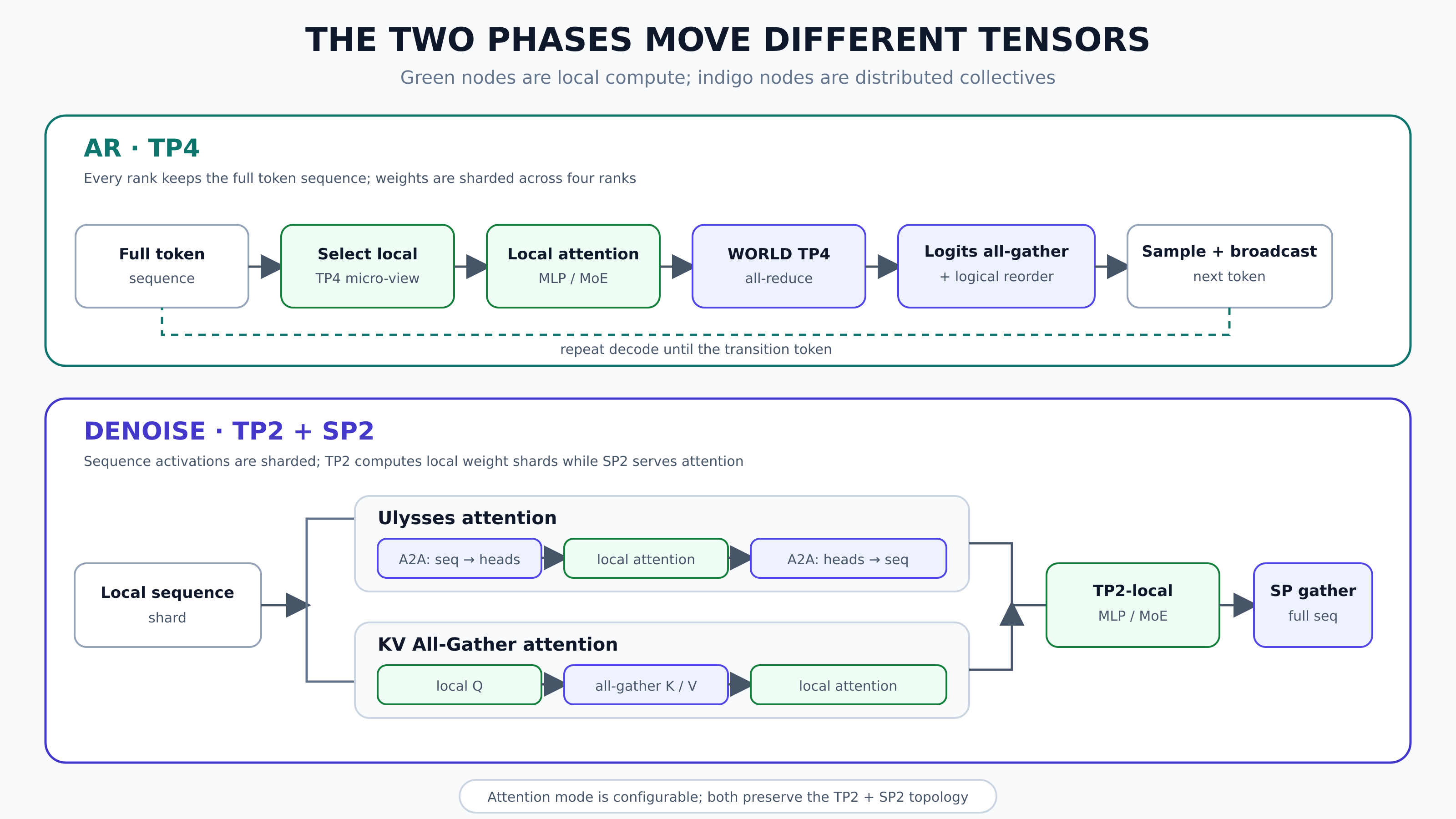
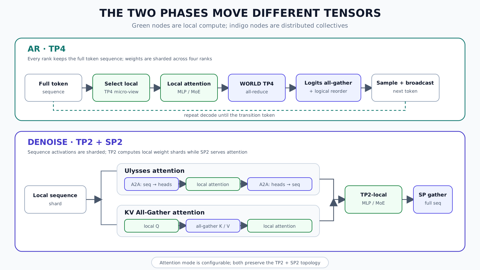
Figure 7: AR retains the complete token sequence and shards the weights; denoise shards sequence activations and supports both Ulysses and KV All-Gather SP attention. SVG source
8. How T2I and TI2I Share the Same Runtime
T2I and TI2I share:
-
phase-aware parallel context;
-
ABAB resident layout;
-
AR TP4;
-
denoise TP2+SP2;
-
multi-micro MoE;
-
KV cache and serial CFG.
TI2I must additionally process a reference image and preserve the condition tensor across the AR→denoise topology switch:
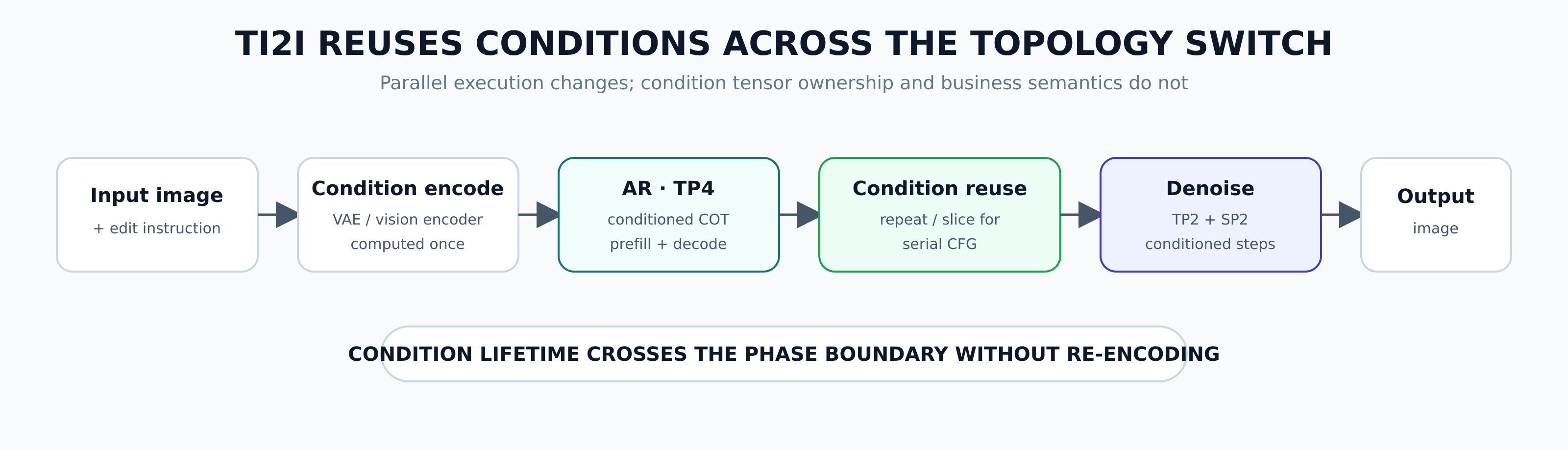
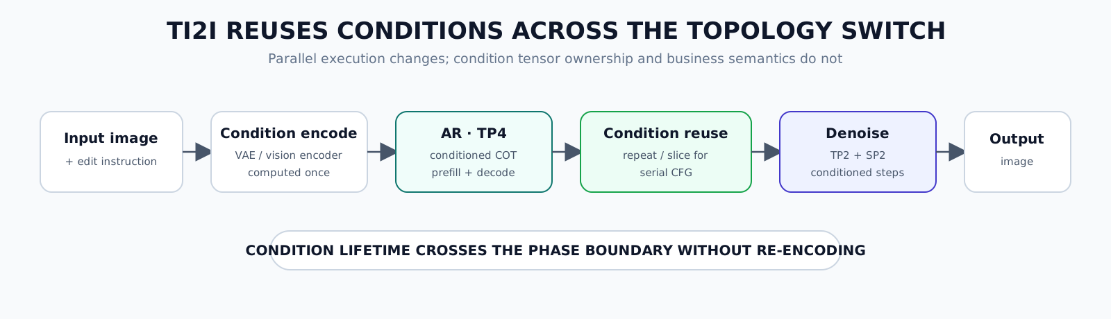
Figure 8: The image condition is encoded only once, participates in COT generation under AR TP4, and is then reused by serial CFG and TP2+SP2 denoise. SVG source
9. Evaluation Methodology
We use synchronized inference latency measured after weight loading as the primary metric and report it by stage:
-
AR prefill, in ms;
-
Total AR decode time over three runs, in s;
-
AR time per token, in ms;
-
DiT one step, in ms;
-
ALL, in s.
In addition, the T2I prefill length is fixed at 1251, and the TI2I prefill length is fixed at 6290. Because the actual number of tokens generated during AR decode differs across schemes, both total decode time and ALL are affected by the token trace. We therefore also report AR time per token as a more precise metric:
time per token
= three-round decode total time
/ three-round generated token count
9.1 Experimental Environment
Hardware: 4×H200-140GB; Warmup/measurement: 2/3; weight loading and file saving are excluded.
10. Comparison of Basic Parallelism Schemes
10.1 T2I
The T2I prefill length is 1251.
| 4 GPUs | AR prefill (ms) | AR decode, 3 rounds (s) | Time/token (ms) | Tokens | DiT one step (ms) | ALL (s) |
|---|---|---|---|---|---|---|
| TP4 | 68.021 | 97.191 | 47.480 | 2047 | 310.748 | 49.125 |
| TP2SP2 | 76.352 | 106.745 | 55.713 | 1916 | 288.530 | 51.158 |
| AR TP4 + DiT TP2SP2 | 66.485 | 104.250 | 46.333 | 2250 | 285.096 | 50.041 |
Compared with fixed TP4, the hybrid scheme is:
-
Approximately 2.26% faster in AR prefill;
-
Approximately 2.42% faster per AR token;
-
Approximately 8.25% faster per DiT step.
Compared with fixed TP2SP2, the hybrid scheme is:
-
Approximately 12.92% faster in AR prefill;
-
Approximately 16.84% faster per AR token;
-
Approximately 1.19% faster per DiT step.
Note that the hybrid scheme generated 2250 tokens over three runs, whereas TP4 generated 2047. As a result, the hybrid scheme has a longer total decode time, and ALL likewise cannot be used directly to assess parallel efficiency in isolation. “AR is 16.84% faster” refers specifically to normalized per-token latency relative to TP2SP2, not the total decode time over three runs.
10.2 TI2I
The TI2I prefill length is 6290.
| 4 GPUs | AR prefill (ms) | AR decode, 3 rounds (s) | Time/token (ms) | Tokens | DiT one step (ms) | ALL (s) |
|---|---|---|---|---|---|---|
| TP4 | 229.588 | 63.614 | 49.621 | 1282 | 357.468 | 40.731 |
| TP2SP2 | 208.489 | 78.521 | 55.871 | 1406 | 336.527 | 44.588 |
| AR TP4 + DiT TP2SP2 | 228.162 | 62.893 | 45.608 | 1379 | 336.162 | 39.410 |
Compared with fixed TP4, the hybrid scheme is:
-
Approximately 0.62% faster in prefill;
-
Approximately 8.09% faster per AR token;
-
Approximately 5.96% faster per DiT step;
-
Approximately 3.24% faster in the observed ALL value for this run.
Compared with fixed TP2SP2, the hybrid scheme is:
-
Approximately 9.44% slower in prefill;
-
Approximately 18.37% faster per AR token;
-
Essentially tied, but approximately 0.11% faster, per DiT step;
-
Approximately 11.61% faster in the observed ALL value for this run.
TI2I’s long prefill includes image-conditioning inputs, which is why TP2SP2 was faster in this prefill measurement. The value of the hybrid scheme is not that it guarantees the best isolated result for every substage, but that it simultaneously achieves better AR decode per-token latency and denoise-step latency while improving the observed end-to-end latency in this run.
10.3 Multi-micro MoE Ablation: Shared Routing vs. Two FlashInfer Dispatches
To isolate the benefit of multi-micro-shard MoE, we added a denoise ablation experiment. Both implementations use exactly the same four-GPU topology, resident weights, and execution flow: AR uses TP4, denoise uses TP2+SP2, weights remain resident in the storage-TP2 ABAB layout, and CFG executes serially. The only difference is how denoise consumes the two micro-shards on each GPU:
-
The Multi-micro path shares one route permutation, expert offsets, and permuted input. After completing the four required grouped GEMMs, it performs routing-scale and top-k finalize only once;
-
The Two-dispatch path invokes the official
flashinfer_cutlass_fused_moeonce for each of the two active micro-shards, adds the two outputs locally, and still performs only one TP2 all-reduce at the end.
T2I:
| Denoise MoE implementation | AR prefill (ms) | AR decode, 3 rounds (s) | Time/token (ms) | Tokens | DiT one step (ms) | ALL (s) |
|---|---|---|---|---|---|---|
| Multi-micro shared routing | 66.485 | 104.250 | 46.333 | 2250 | 285.096 | 50.041 |
| Two FlashInfer dispatches | 67.192 | 96.064 | 47.021 | 2043 | 309.167 | 48.644 |
For T2I, the DiT per-step latency of two FlashInfer dispatches is 8.44% higher than that of multi-micro. Equivalently, multi-micro reduces per-step latency from 309.167 ms to 285.096 ms, a reduction of 7.79%. The ALL value of Two-dispatch appears lower, but it generated only 2043 decode tokens over three runs, whereas multi-micro generated 2250. The 1.397 s difference therefore cannot be attributed to the denoise implementation.
TI2I:
| Denoise MoE implementation | AR prefill (ms) | AR decode, 3 rounds (s) | Time/token (ms) | Tokens | DiT one step (ms) | ALL (s) |
|---|---|---|---|---|---|---|
| Multi-micro shared routing | 228.162 | 62.893 | 45.608 | 1379 | 336.162 | 39.410 |
| Two FlashInfer dispatches | 227.934 | 64.680 | 46.599 | 1388 | 352.516 | 40.821 |
For TI2I, the DiT per-step latency of two FlashInfer dispatches is 4.86% higher than that of multi-micro. Multi-micro reduces per-step latency from 352.516 ms to 336.162 ms, a reduction of 4.64%. The two groups generated similar numbers of decode tokens, 1388 and 1379, respectively; in this run, the ALL value of Two-dispatch was also 3.58% higher.
The results for both tasks show that the benefit of the multi-micro path does not come from reducing the number of MoE GEMMs. GEMM1 and GEMM2 must still be executed for each of the two micro-shards. What it eliminates is the duplicated dispatch, workspace, and finalize overhead of a second complete FlashInfer invocation.
11. Comparison with Other Parallelism Optimizations
The unified benchmark report also includes the LightX2V integration results for FlexTP, Flying Serving, Moebius, and ReMP.
11.1 Extended T2I Results
| Scheme | AR prefill (ms) | AR decode, 3 rounds (s) | Time/token (ms) | Tokens | DiT step (ms) | ALL (s) |
|---|---|---|---|---|---|---|
| Hybrid TP4 → TP2SP2 | 66.485 | 104.250 | 46.333 | 2250 | 285.096 | 50.041 |
| FlexTP, threshold=4096 | 86.744 | 95.725 | 53.899 | 1776 | 286.860 | 47.478 |
| Flying Serving, low load | 66.477 | 96.232 | 47.196 | 2039 | 309.755 | 48.774 |
| Flying Serving, high load | 86.107 | 93.679 | 52.747 | 1776 | 451.376 | 54.974 |
| Moebius, low load | 66.643 | 97.830 | 46.409 | 2108 | 310.476 | 49.300 |
| Moebius, high load | 325.419 | 143.777 | 63.394 | 2268 | 1804.841 | 139.599 |
| ReMP, low concurrency | 76.178 | 97.795 | 48.897 | 2000 | 312.005 | 48.789 |
| ReMP, medium/high concurrency | 216.048 | 224.398 | 115.194 | 1948 | 1122.923 | 132.600 |
| ReMP, high concurrency | 343.259 | 227.224 | 109.929 | 2067 | 1743.826 | 166.041 |
11.2 Extended TI2I Results
| Scheme | AR prefill (ms) | AR decode, 3 rounds (s) | Time/token (ms) | Tokens | DiT step (ms) | ALL (s) |
|---|---|---|---|---|---|---|
| Hybrid TP4 → TP2SP2 | 228.162 | 62.893 | 45.608 | 1379 | 336.162 | 39.410 |
| FlexTP, threshold=4096 | 228.266 | 64.891 | 46.886 | 1384 | 336.898 | 40.098 |
| Flying Serving, low load | 227.879 | 61.026 | 46.907 | 1301 | 356.061 | 39.777 |
| Flying Serving, high load | 331.095 | 73.283 | 53.104 | 1380 | 533.434 | 52.770 |
| Moebius, low load | 228.038 | 59.077 | 46.554 | 1269 | 355.491 | 39.119 |
| Moebius, high load | 1353.773 | 79.739 | 62.541 | 1275 | 2014.439 | 130.059 |
| ReMP, low concurrency | 239.724 | 66.404 | 47.534 | 1397 | 370.800 | 41.783 |
| ReMP, medium/high concurrency | 922.188 | 142.730 | 113.008 | 1263 | 1273.305 | 114.853 |
| ReMP, high concurrency | 1465.401 | 155.855 | 110.692 | 1408 | 2337.071 | 175.428 |
The current data support the following conclusions:
-
The hybrid scheme achieves the lowest AR time/token for both T2I and TI2I.
-
The hybrid scheme achieves the lowest DiT one-step latency for both tasks.
12. Configuration and Usage
The core fields of the hybrid-parallel configuration are as follows:
{
"moe_impl": "flashinfer",
"flashinfer_multi_micro": true,
"flashinfer_multi_micro_backend": "grouped_mm",
"parallel": {
"phase_aware": true,
"storage_tensor_p_size": 2,
"ar": {
"tensor_p_size": 4,
"seq_p_size": 1
},
"denoise": {
"tensor_p_size": 2,
"seq_p_size": 2
},
"cfg_p_size": 1,
"seq_p_attn_type": "ulysses",
"cfg_mode": "serial"
}
}
T2I:
CUDA_VISIBLE_DEVICES=0,1,2,3 bash scripts/hunyuan_image3/run_hunyuan_image3_t2i_ar_tp4_denoise_tp2_sp2_multi_micro_flashinfer.sh
TI2I:
CUDA_VISIBLE_DEVICES=0,1,2,3 bash scripts/hunyuan_image3/run_hunyuan_image3_ti2i_ar_tp4_denoise_tp2_sp2_multi_micro_flashinfer.sh
13. Conclusion
The central parallelism challenge in Hunyuan Image 3.0 is not selecting a single globally optimal TP or SP degree, but accommodating two execution stages that require different compute topologies: TP4 for AR and TP2+SP2 for denoise.
LightX2V first organizes the complete official weight set M into storage-TP2 shards A/B according to each layer’s TP semantics. Because denoise contains two SP replicas, these A/B shards naturally form ABAB across four GPUs and become the sole resident layout. The key property that makes this scheme possible is that the AR TP4 shard on each GPU is exactly one micro-subset of its resident denoise A/B shard. AR activates this subset; denoise activates the complete parent shard already resident on the GPU and switches to the pre-created TP2+SP2 process groups. At phase boundaries, only the active topology and weight view change; resident weights are neither reloaded nor moved.
MoE is the part of this design that requires dedicated adaptation. The Multi-micro path preserves micro-major storage and shares the route permutation, expert offsets, and final reduction, allowing denoise to consume two micro-shards directly without rearranging weights or executing two complete dispatch pipelines.
The current results show that this design simultaneously lowers AR per-token latency and DiT per-step latency for both T2I and TI2I. More importantly, it suggests a general engineering principle for unified generative models: rather than forcing heterogeneous stages to share one parallel strategy, switch the communication topology and compute view by phase while keeping expensive model state resident whenever possible.